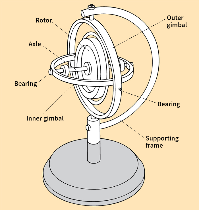
Gyroscope, << JY ruh skohp, >> also called a gyro, is a device that uses rotation to produce a stable direction in space. A mechanical gyroscope, the oldest type of gyroscope, consists of a spinning wheel or ball, called the rotor, and a support system. Once the rotor is set in motion, the gyroscope resists any attempt to change its direction of rotation. Because of this property, gyroscopes are widely used in flight and navigation instruments. Several modern types of gyroscopes provide directional information without using a spinning rotor.
A gyroscopic instrument called the turn and slip indicator or turn-and-bank indicator helps pilots maintain the desired course of their aircraft in flight. Automatic flight control systems, also called automatic pilots, use gyros to steer a ship or plane closer to a course than a human pilot could. Gyroscopic devices also guide torpedoes, missiles, satellites, and space vehicles.
Gyroscopic properties
Gyroscopes are useful for detecting changes in direction because of the properties of spinning bodies. All spinning bodies demonstrate (1) gyroscopic inertia and (2) precession.
Gyroscopic inertia
is the tendency of a spinning body to resist any attempt to change the direction of its axis of rotation. For example, Earth spins around its axis, an imaginary line that connects the North and South poles. Because of gyroscopic inertia, the North Pole of Earth continues to point to the North Star as Earth moves in its orbit around the sun.
Gyroscopic inertia enables the axis of a spinning gyroscope always to point in the same direction, no matter how the support of the gyroscope moves about. The magnitude (strength) of the inertia depends on the distribution of the weight of the rotor and the speed of its spin. Gyroscopes with most of their weight at the rotor’s rim have the greatest amount of inertia. Thus, a bicycle wheel makes a good gyroscope, but a pencil spinning on its point does not. In addition, the faster the rotor spins, the more gyroscopic inertia it possesses.
Precession
is the tendency of a spinning body to move at right angles to the direction of any force that tries to change its direction of rotation. You can use precession to guide a rolling hoop. When you roll the hoop, it will not fall down if you push from the side against the top. In this case, the hoop merely turns a corner. The hoop precesses, or turns at right angles to the force that you have applied against it. Similarly, a spinning gyroscope will move at right angles to any force that attempts to change the direction of its axis. The earth itself precesses slightly because of the pull of gravity by the sun and moon.
Kinds of gyroscopes
Mechanical gyroscopes
commonly consist of a rotor and axle supported by a fixed frame and base. In a single-degree-of-freedom gyroscope, the rotor and axle are mounted on a ring, called a gimbal, that pivots inside the gyroscope’s frame. The gyro can then rotate freely around an imaginary line running perpendicular to the rotor’s axle. To allow the gyroscope to rotate in a second direction, the gimbal can be mounted on bearings inside another gimbal. A frame and base support both gimbals, and the gyroscope’s axle is then free to point in the same direction no matter how the frame is held. Gyroscopes with two gimbals are called two-degree-of-freedom gyroscopes.

Gyroscope rotors are driven by an electric motor or high-speed jets of air. Rotors vary greatly in size. Those used in aircraft instruments may be smaller than 2 inches (5 centimeters) across and rotate 30,000 times a minute. Three huge gyroscope rotors, each 13 feet (4 meters) across, were built in 1933 for the gyrostabilizers in the ocean liner Conte Di Savoia. Each weighed 110 tons (100 metric tons) and rotated 800 times a minute.
The bearings on which a mechanical gyroscope rotates must be made with great accuracy, so that they will have as little friction as possible. Friction causes the rotor’s axis to drift away from the proper direction. The best mechanical gyroscopes use ball bearings that are almost perfectly smooth and round. These gyroscopes are assembled in special windowless clean rooms because even a speck of dust can affect a gyroscope’s performance. Rotors can also be cushioned to minimize friction by floating the rotor in liquid or supporting the bearings with a thin layer of pressurized gas.
Electrically suspended gyroscopes
use a light ball of the metal beryllium as the rotor. The rotor in these gyroscopes is a light ball of the metal beryllium. The ball is suspended in a vacuum by electric forces and then is sent spinning by magnetic forces.
Optical gyroscopes
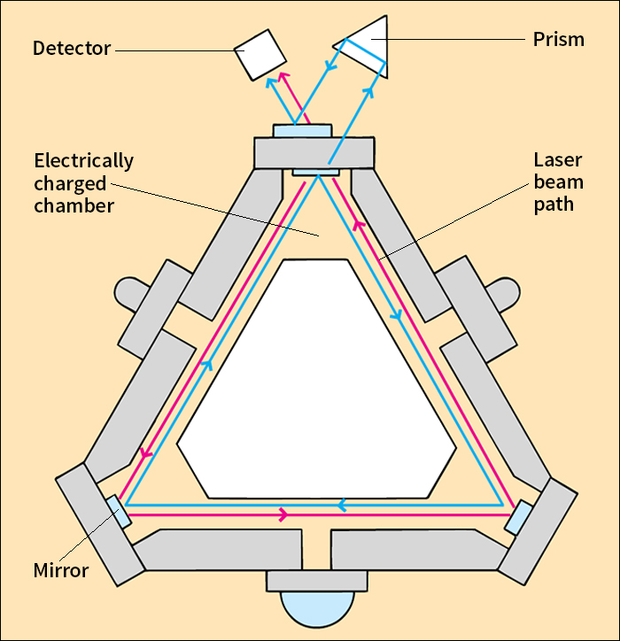
do not have a spinning rotor. In these devices, two beams of laser light travel in opposite directions around a path known as a ring. Initially, the light waves are in step with one another. However, if the gyro is tilted—as when an airplane turns—one of the beams must travel farther than the other to complete the ring. The beams will thus become out of step. Computers then analyze how much the beams are out of step and compute the plane’s change in direction.

There are two types of optical gyroscopes: ring laser gyros (RLG’s) and fiber-optic gyros (FOG’s). In an RLG, the ring is a triangular or rectangular path with mirrors at each corner to redirect the two beams of light. In a FOG, the ring is a coil of transparent glass thread known as optical fiber.
Vibrating gyroscopes
include tiny, highly sensitive components made of quartz or silicon. The main component is a sensor shaped like a tuning fork, a wine glass, or a triangular prism. Any change in direction of motion results in a bending force around the axis of the sensor. Other sensors in the gyroscope measure the stresses on the axis and convert the information to numerical data that can be interpreted by a computer.
History
The first gyroscope that resembled modern mechanical gyroscopes was made by G. C. Bohnenberger, a German inventor, in 1810. In 1852, Jean Foucault, a French physicist, built a gyroscope to demonstrate that the earth rotates on its axis. Foucault named the instrument from two Greek words—gyros, meaning circle or ring, and skopein, meaning to view—because the gyroscope had enabled him to view the revolution of the earth.
The first gyroscopically controlled devices were torpedoes developed during the 1890’s. In 1908, Hermann Anschütz-Kämpfe, a German engineer, invented the gyrocompass. This gyro-controlled device was not affected by magnetic fields as were other compasses. In 1911, Elmer A. Sperry, an American scientist, inventor, and manufacturer, developed an improved gyrocompass for ships. Sperry also produced some of the first gyroscopic flight instruments. The rate-of-turn indicator, the directional gyro, and the artificial horizon were used in aircraft during World War II (1939-1945). These instruments permitted safe flight at night and precise landing approaches through clouds.
In the late 1940’s and early 1950’s, scientists at the Massachusetts Institute of Technology built the first highly accurate inertial guidance systems. Such systems use gyroscopes and other guidance devices to keep a vehicle on its course (see Inertial guidance ).
Electrically suspended gyroscopes date from the 1950’s. The development of optical gyroscopes began in the 1960’s. Vibrating gyroscopes were introduced in the 1990’s.
See also Automatic flight control system (AFCS) ; Foucault, Jean B. L. ; Gyrocompass ; Gyrostabilizer ; Sperry, Elmer A .
