Electric motor is a machine that changes electric power into mechanical power to do work. Electric motors are used to operate a variety of machines and machinery. Washing machines, air conditioners, and vacuum cleaners include electric motors, as do hairdryers, sewing machines, and power drills and saws. Various kinds of motors power machine tools, robots, and other equipment to keep factories running smoothly.

The size and capacity of electric motors vary widely. An electric motor may be a tiny device that functions inside a wrist watch or a huge engine that powers a heavy locomotive. Blenders and most other kitchen appliances use small motors because they need just a little power. Trains require larger and more complex motors because the motor must accomplish a great deal of work within a short time.
There are two general types of electric motors, based on the type of electricity they use. They are (1) alternating current (AC) motors and (2) direct current (DC) motors. Alternating current usually reverses the direction of its flow 60 times per second. Alternating current is available from electrical outlets in homes, and so AC motors are commonly used in household appliances. Direct current flows in only one direction. Its chief source is a battery. DC motors are commonly used to run machinery in factories. They are also used as starters for gasoline engines. See Electric current.
Loading the player...Direct-current motor
Electric motors depend on electromagnets to produce the force that is necessary for driving a machine or machinery. The machine or machinery driven by an electric motor is known as its load. A drive shaft connects the motor to the load.
Basic principles
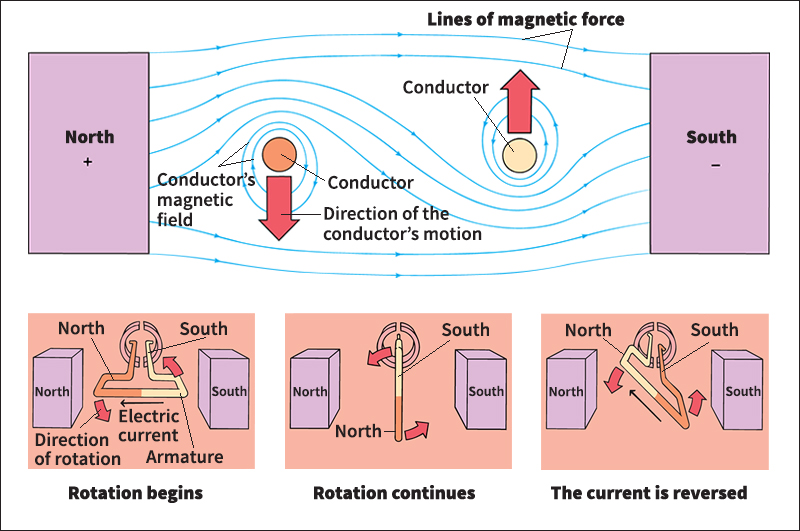
The operation of an electric motor is based on three main principles: (1) An electric current produces a magnetic field; (2) the direction of a current in an electromagnet determines the location of the magnet’s poles; and (3) magnetic poles attract or repel each other.
When an electric current passes through a wire, it produces a magnetic field around the wire. If the wire is wound in a coil around a metal rod, the magnetic field around the wire becomes strengthened and the rod becomes magnetized. This arrangement of rod and wire coil is a simple electromagnet, with its two ends serving as north and south poles. See Electromagnet.
The right-hand rule is one way of showing the relationship between the direction of the current and the magnetic poles. Hold a coil of wire in your right hand. Supposing the coil is an electromagnet, wrap your fingers around it so that they point in the direction of the current. Your thumb then points toward the electromagnet’s north pole. This method works only when a current flows from a positive terminal to a negative one.
Like poles, such as two north poles, repel each other. Unlike poles attract each other. If a bar magnet is suspended between the ends of a horseshoe magnet, it will rotate until its north pole is opposite the horseshoe magnet’s south pole. The bar magnet’s south pole will be opposite the horseshoe magnet’s north pole.
Parts of an electric motor
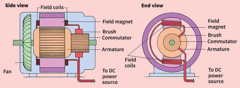
An electric motor consists chiefly of a rotating electrical conductor situated between the north and south poles of a stationary magnet. The conductor is known as the armature, and the stationary magnet is called the field structure. A commutator is also an essential part of many electric motors—especially DC motors.
The field structure
establishes a constant magnetic field in the motor. The magnetic field consists of lines of force that exist between the poles of the stationary magnet. In a small, simple DC motor, the field structure consists of a permanent magnet called a field magnet. In some larger or more complex motors, the field structure is made up of one or more electromagnets that are fed electric current from an outside power source. Such electromagnets are known as field coils.
The armature,
which is usually cylindrical in shape, becomes an electromagnet when a current passes through it. It is connected to a drive shaft so that it can drive a load. In a small, simple DC motor, the armature rotates between the poles of the field magnet until its north pole is opposite the south pole of the magnet. The direction of the current is then reversed to change the north pole of the armature into a south pole. The two south poles repel each other, causing the armature to make another half turn. When the armature’s two poles are next to opposite poles of the field magnet once more, the direction of the current is again changed.
Each time the direction of the current is reversed, the armature rotates a half turn. The armature would stop moving if the direction of the current were not reversed. When the armature turns, it cuts the lines of magnetic force created by the field structure. Cutting the magnetic field produces a voltage in the opposite direction of the driving force. This voltage, called a counter-electromotive force, reduces the speed of rotation of the armature, as well as the current it carries. If a motor drives a light load, the armature will spin rapidly and generate a large counter-electromotive force. When the load is increased, the armature rotates more slowly. It cuts fewer lines of magnetic force, thereby decreasing the counter-electromotive force. A motor that carries a heavier load thus operates more efficiently, because it uses less energy to do more work.
The commutator
is used mainly in DC motors. It reverses the direction of the current in the armature and helps transmit the current between the armature and the power source. For a DC motor, the commutator consists of two or more semicircular split rings, which are fixed to the drive shaft, next to the armature. Each end of the armature coil is attached to a different ring.
The electric current from the external power source is conducted to the commutator by a small block called a brush. Another brush, located on the other side of the commutator, carries the current back to the power source. When one of the rings comes into contact with the first brush, it picks up the electric current from the brush and sends it through the armature. When the magnetic poles thereby created in the armature are next to like poles of the field magnet, the armature rotates a half turn, past one of the gaps separating the rings. The second ring of the commutator then comes into contact with the first brush and becomes the carrier of the electric current to the armature. In this way, the direction of the current has been reversed, as has the location of the poles in the armature. Like poles of the field magnet and the armature are once again opposite each other, and the armature continues to turn.
Most AC motors do not have commutators because alternating current reverses its direction independently. In AC motors that do have commutators, the commutator simply conducts the current from the external power source to the moving part of the motor and back. It consists of a round slip ring instead of split rings.
Kinds of electric motors
DC motors
require commutators to reverse the direction of the current. There are three main kinds of DC motors—series, shunt, and compound motors. They differ from one another chiefly in the circuit arrangement between the armature and the field structure.

In a series motor, the armature and the field magnet are connected electrically in series. The current flows through the field magnet and then the armature. As the current flows through the structures in this order, it increases the strength of the magnets. A series motor can start quickly, even with a heavy load. However, such a load will decrease the motor’s speed.
In a shunt motor, the magnet and the armature are connected in parallel. One part of the current goes through the magnet while the other part passes through the armature. A fine wire is wound around the field magnet many times in order to increase the magnetism. Constructing the field magnet in this way also creates further resistance to the current. The strength of the current and the level of magnetism therefore depend on the resistance of the wire rather than the load on the motor. A shunt motor will run at an even speed regardless of the load. However, if the load is too heavy, the motor will have problems starting.
A compound motor has two field magnets connected to the armature—one in series, the other in parallel. Compound motors have the benefits of both the series and the shunt motor. They can start easily with a heavy load and maintain a relatively constant speed, even if the load is suddenly increased.
AC motors
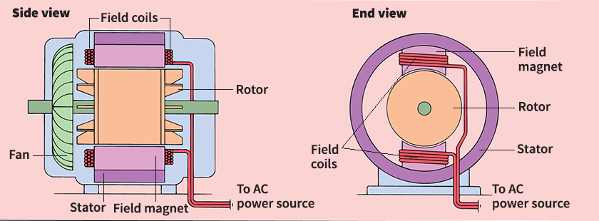
are easy to build and convenient to use. They do not require commutators, and most of them operate on current provided by electrical outlets in households. In an AC motor, the moving part is often called the rotor, and the stationary part is frequently known as the stator. The most common AC motors include induction motors and synchronous motors.

The rotor of an induction motor consists of a cylindrical iron core with slots along its length. Copper bars fit into the slots and are fastened to a thick copper ring at each end. The rotor has no direct connection to the external source of electric current. The alternating current flows around the field coils in the stator and produces a rotating magnetic field. This field induces (creates) an electric current in the rotor, resulting in another magnetic field. The magnetic field from the rotor interacts with the magnetic field from the stator, causing the rotor to turn.
The stator in a synchronous motor also produces a rotating magnetic field. But the rotor receives current directly from the power source instead of relying on the magnetic field from the stator to induce an electric current. The rotor moves at a fixed speed in step with the rotating field of the stator. The speed is proportional to the frequency with which the alternating current supplied to the stator reverses. Because this frequency is usually fixed, synchronous motors, like shunt and compound DC motors, maintain a consistent speed, even with a changing load. They also use less energy. These motors are ideal for clocks and telescopes, which require precise timing and smooth turning.
Universal motors
are built to operate on either DC or AC electric current. A universal motor uses a commutator, and its basic construction resembles the design of a DC series motor. On DC, it performs like a series motor. If AC is used, the magnetic poles of the armature and the field coils reverse with the frequency of the current. Universal motors are popular in many appliances because of their flexibility.
History
The development of electric motors began in the 1800’s with the discovery of electromagnets. In 1820, a Danish physicist named Hans Christian Oersted discovered that a wire conducting an electric current produces a surrounding magnetic field. During the 1820’s, a number of other scientists found ways of creating stronger and more practical electromagnets. In 1825, William Sturgeon, an English electrician, wrapped a conductor around an iron bar to produce a stronger electromagnet. In the late 1820’s, the American physicist Joseph Henry showed that an even more powerful electromagnet could be made by wrapping several layers of insulated wire around a piece of iron. Also in the 1820’s, the French mathematician and physicist Andre Marie Ampere developed mathematical theories describing the behavior of electric currents and magnets.
In the early 1830’s, Henry and the English physicist Michael Faraday independently found that magnetic fields could be used to create current in a coil of wire. This knowledge of electromagnetic induction led to the invention of electric generators and other devices. In 1832, Ampere’s instrument maker, the Frenchman Hippolyte Pixii, devised a split-ring commutator that received electric current from a DC generator.
In 1873, the first commercially successful DC motor was demonstrated in Vienna at an exhibition by Zenobe Theophile Gramme, a Belgian electrical engineer. Gramme also introduced an armature that improved the efficiency of early electric motors and generators.
In 1888, a Serbian-born engineer named Nikola Tesla invented the AC motor. Tesla designed models for induction and synchronous motors. In the early 1900’s, scientists and engineers developed more advanced electric motors, including universal motors.
