Telescope is an instrument that magnifies distant objects. A telescope can also produce images of objects that are too faint to see with the unaided eye. Astronomers use telescopes to study the planets, stars, and other heavenly bodies.
Telescopes vary in shape and size from binoculars that can be held in the hands to bowl-shaped reflectors that measure up to 1,000 feet (305 meters) across. A pair of binoculars is actually two telescopes joined side by side. There are telescopes in large, dome-shaped buildings on the surface of Earth and telescopes in artificial satellites in orbit around Earth. Space probes that journey to other planets also carry telescopes.
The most familiar telescopes are optical telescopes. These instruments, like our eyes, work with visible light. In an optical telescope, a mirror or lens collects the light and uses it to form an image. Small telescopes used by amateur astronomers also have an eyepiece containing small lenses for viewing the image. But professional astronomers rarely look through the large optical telescopes they use. Instead, they record the image with an electronic sensor called a charge-coupled device (CCD) or, less often, with photographic film. A CCD in a large telescope is a more powerful version of the device that takes the pictures in an ordinary digital camera.
Objects in space also emit (give off) many kinds of radiation that people cannot see, such as radio waves, ultraviolet rays, and even X rays. Astronomers use other kinds of telescopes equipped with electronic detectors to form images with this radiation.
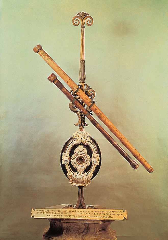
The Dutch optician Hans Lippershey probably made the first telescope—an optical telescope—in 1608. Lippershey mounted two glass lenses in a narrow tube. In 1609, the Italian astronomer and physicist Galileo made the first practical use of the refracting telescope to discover new facts about astronomy. In 1668, English scientist, astronomer, and mathematician Isaac Newton built a telescope that used a mirror instead of lenses. Today, most large optical telescopes use mirrors.
What telescopes do
Telescopes detect visible light and other forms of electromagnetic radiation that move through space in waves. The various forms of radiation differ in wavelength—that is, the distance between the crest of one wave and the crest of the next. The forms of electromagnetic radiation are—from the longest to the shortest wavelength—radio waves, infrared rays, visible light, ultraviolet rays, X rays, and gamma rays. These different forms of radiation also carry different amounts of energy in small units called photons. The shorter a photon’s wavelength, the higher its energy.
Telescopes perform three main tasks: (1) they produce images of distant objects in fine detail; (2) they detect objects that are too faint to see with the unaided eye; and (3) they gather light for spectrographs, devices that analyze the light.
Producing detailed images.
Astronomers call a telescope’s ability to produce images in fine detail its resolution or resolving power. Resolution is a measure of the ability to show that objects which appear to be together are clearly separate. A telescope does this by magnifying the image of the objects, enabling astronomers to get a “closer view.”
High magnification is relatively easy to achieve, but it is less important than high resolution. There is no value in magnifying an image more than necessary to see the smallest detail. A high magnification of an image formed by a telescope with a low resolution would produce a large picture, but the picture would be blurry.
Telescopes used by amateur astronomers have about 100 times the resolution of the unaided eye. The following example may help you understand this comparison: Suppose you go outdoors without a telescope and look at a group of what seem to be single stars. Then you concentrate on one of the brighter stars, and you realize that this “star” is actually two stars. You have resolved the stars. But suppose you were to use an optical telescope with 100 times the resolution of the unaided eye. You could then as easily resolve two stars that are 100 times closer together than the first pair of stars.
The resolution that a telescope can achieve in perfect viewing conditions depends mainly on the diameter of its mirror or lens and the wavelength of the radiation collected. The larger the mirror or lens and the shorter the wavelength, the higher the resolution. But viewing conditions for ground-based optical telescopes are far from perfect. Wind and daily heating and cooling of the atmosphere produce pockets and swirls of warm and cool air. The differences in air temperature affect the speed and direction of light through the air. Light waves become distorted, so the telescope produces a blurred image.
To achieve high resolution in spite of atmospheric blurring, astronomers are beginning to install special equipment called adaptive optics on ground-based telescopes. In the mid-1990’s, astronomers began to install adaptive optics on large telescopes that collect visible light and infrared rays.
Orbiting observatories avoid atmospheric blurring by operating in space, above almost all the air. The Hubble Space Telescope has produced thousands of images that are 10 times sharper than images made by ground-based telescopes without adaptive optics.
Detecting faint objects.
A telescope’s ability to detect faint objects depends, like the telescope’s resolution, on the diameter of the main mirror or lens. Huge optical telescopes can gather about 1 million times more light than the unaided eye. These telescopes therefore can detect objects about 1 million times fainter than objects that are visible with the unaided eye.
The use of photographic film and CCD’s further increases the advantage of optical telescopes over the unaided eye. If film is exposed to a dim object for a long time, a bright picture results. Thus, photographs of the sky taken through a telescope reveal many details that could not be seen through an eyepiece attached to the telescope. In the mid-1970’s, astronomers began to use CCD’s instead of film because the CCD’s are about 50 times more sensitive to light than film is. A CCD translates the light that strikes it into electric charges, which produce signals used to form images on a computer screen. Electronic sensors that detect invisible forms of electromagnetic radiation work similarly.
Gathering light for spectrographs.
Most research telescopes also reflect light to devices called spectrographs. A spectrograph breaks up the light, spreads it out into its different colors, and records it for analysis. The band of spread-out light is known as a spectrum (plural spectra). The most familiar spectrum is the band of colored light in a rainbow, produced when raindrops break up and spread out sunlight. Astronomers analyze spectra to determine the chemical composition and temperature of stars, planets, and gas clouds, and to calculate how fast an object is approaching or moving away from Earth.
Optical telescopes
There are three main types of optical telescopes: (1) refracting telescopes, (2) reflecting telescopes, and (3) refracting-reflecting telescopes. All three types operate according to the same principles.
Light waves from distant objects in the universe arrive at Earth with their crests a succession of almost perfectly flat planes. These planes are parallel to one another but strike the ground at an angle—unless the object being viewed is directly overhead. Each crest is known as a wave front. The main mirror or lens gathers a wide section of a wave front and brings the waves together at a point called the focus.
Wave fronts from stars in different parts of the sky concentrate at different points. All these points, however, lie an equal distance from the mirror or lens in an area called the focal plane. The distance from a mirror or lens to its focal plane is called the focal length. If you were to place a sheet of paper at the focal plane, you would see an image of the part of the sky “viewed” by the mirror or lens. To record an image, astronomers place a CCD or photographic film at the focal plane. For direct observation, an eyepiece would replace the CCD or film. The eyepiece magnifies the image. The magnifying power of the telescope equals the focal length of the mirror or lens divided by the focal length of the eyepiece.
Refracting telescopes,
also called refractors, have a large lens called an objective lens—or simply an objective—at one end of a long, narrow tube. The objective is convex (curved outward) on both sides so that the middle of the lens is thicker than the edges. The glass slows down the light waves as they pass through the lens. A wave slows down the most in the middle of the lens, where the glass is thickest. At the ends of the lens, where the glass is thinnest, the wave slows down the least. The speed differences cause the wave crests to curve so that they arrive at the same place—the focus—at the same time.
Galileo made all his discoveries using refracting telescopes. Galileo’s instruments and other early refractors, however, produced images with rainbow coloring around the edges called chromatic aberration. This coloring appeared because a convex lens slows down different colors of light passing through it by different amounts. For example, the lens slows down violet light more than red. As a result of this difference in speed, a wave front of violet light curves to a shorter focus than does a wave front of red light. wave fronts whose focal lengths were significantly shorter or longer than that of the image produced the rainbow coloring.
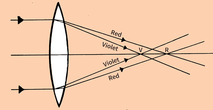
Astronomers found that less-curved lenses produced less chromatic aberration. But these lenses had long focal lengths and therefore required extremely long tubes. Some early telescopes were more than 200 feet (60 meters) long. In the early 1800’s, however, German optician Joseph von Fraunhofer found a way to avoid building such long telescopes. He fitted together two lenses made of different types of glass. The resulting compound lens had a short focal length and produced almost no chromatic aberration.
Reflecting telescopes,
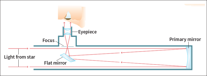
also called reflectors, use bowl-shaped mirrors instead of lenses. The bowl-shaped mirror, called the primary mirror, has a surface shaped so that any line across its center is a parabola, a curve like the path of a ball batted high in the air. A mirror with this shape reflects light rays to a sharp focus. A secondary mirror reflects the rays to a CCD, a piece of photographic film, or an eyepiece.
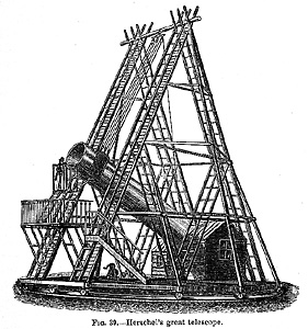
Astronomers generally prefer reflecting telescopes to refracting telescopes because mirrors have some advantages over lenses. The weight of a large lens can cause it to bend and warp. But a large, heavy mirror can be supported from behind. As a result, mirrors can be made much larger than lenses and, thus, can gather more light. In addition, mirrors are useful because they can also collect infrared rays and ultraviolet rays, which are absorbed by glass lenses. Finally, because they do not refract light, mirrors do not produce chromatic aberration.
Isaac Newton’s first reflecting telescope used a small, flat mirror to reflect light from the primary mirror to an eyepiece at the side of the telescope tube. In 1672, a French telescope maker known as Cassegrain designed a telescope using a small convex mirror in front of the primary mirror. The small mirror reflected the light through a hole in the primary mirror to an eyepiece behind it. Astronomers now use this design for most optical and infrared telescopes.
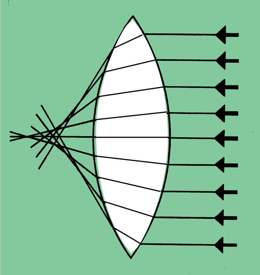
The mirrors of early reflecting telescopes were shaped like a section of a sphere rather than a parabola. The main reason for using spherical mirrors was that they are much easier to grind and polish to the proper shape. However, spherical mirrors produce another form of aberration, a blurring called spherical aberration.
To avoid both chromatic and spherical aberration, scientists developed ways to make parabolic mirrors in the early 1700’s. They made early mirrors of speculum metal, a mixture of copper and tin. But this mixture tarnishes easily, so the mirrors required repeated polishing. In the mid-1800’s, German chemist Justus von Liebig learned how to deposit a thin coating of silver on glass to produce a brilliantly reflecting surface. When the surface tarnished or dulled, he could recoat it without having to polish it. Today, almost all reflecting telescopes have glass mirrors, most of them coated with aluminum.
The first telescope to use a large glass mirror was built in 1908 on Mount Wilson, near Pasadena, California. It is a Cassegrain telescope with a mirror 60 inches (1.5 meters) in diameter. Telescope designers still use the Mount Wilson telescope as a model for most large telescopes. For many years, the largest was the Hale Telescope, an instrument with a 200-inch (5-meter) mirror. This telescope, located on Palomar Mountain in southwestern California, began operating in 1948.
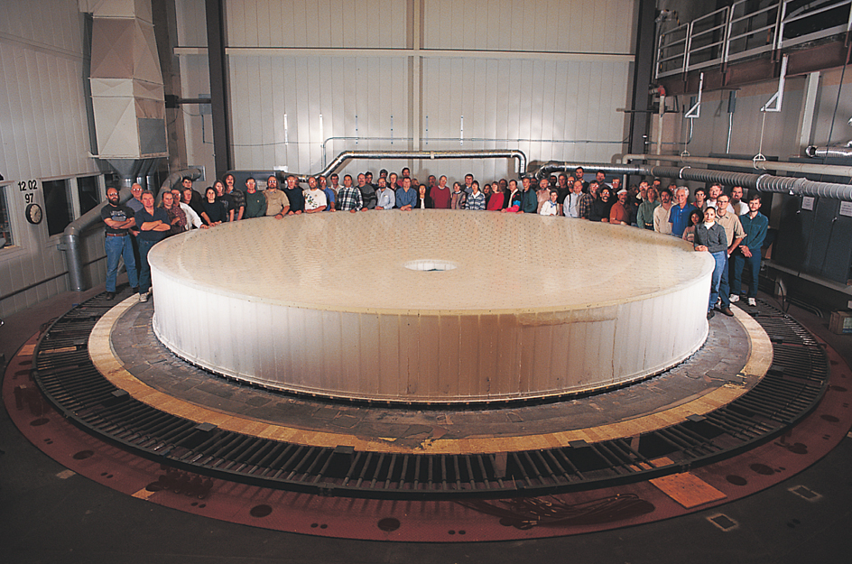
In the 1980’s, astronomers began to work on a new generation of telescopes whose mirrors are larger and smoother than any built before. Like a large lens, a huge mirror of ordinary design would bend or warp under its own weight. Several new designs, including segmented mirrors, thin-disk mirrors, honeycomb mirrors, and liquid mirrors overcame this limitation on mirror size. Some of the new telescope mirrors were made by an advanced technique called spin-casting, which replaces much of the costly, laborious process of grinding. In spin-casting, a huge rotating oven spins melted glass at a carefully controlled speed. The liquid glass flows into a shape that is nearly perfect for a telescope mirror.
Segmented mirrors
consist of several small mirrors designed to do the job of one large mirror. Two identical telescopes called Keck I and Keck II have segmented mirrors. Each consists of 36 hexagonal (six-sided) mirrors mounted close together. These mirrors form a reflecting surface 33 feet (10 meters) in diameter. An electronic sensing system helps hold the segments in place. If a segment gets out of position, sensors on its edges activate pistons in the support structure that move the segment. The two Keck telescopes are on Mauna Kea, a mountain on the island of Hawaii.
Thin-disk mirrors
use computer-controlled pistonlike devices called actuators to maintain the shape of a thin disk of glass. Four identical telescopes that belong to a group of instruments known as the Very Large Telescope (VLT) use this design. Each individual telescope has a mirror 27 feet (8.2 meters) in diameter, but only 7 inches (18 centimeters) thick. When all four telescopes are focused on the same object, they will have the light-gathering power of a single telescope with a mirror 52 feet (16 meters) in diameter. The European Southern Observatory (ESO), led by astronomers from several European nations, built the VLT on Paranal Mountain in Chile. All four telescopes were making observations by September 2000.
Honeycomb mirrors
are made from a mold filled with hundreds of hexagonal blocks of an aluminum and silicon compound. Melted glass covers the blocks and fills the spaces between them. Workers remove the blocks after the glass cools, leaving a stiff structure that is so light it could float on water.
In the late 1990’s and early 2000’s, astronomers at the University of Arizona’s Steward Observatory used this design to make two giant mirrors for the Large Binocular Telescope (LBT) on Mount Graham in southeastern Arizona. Each mirror measures 27.6 feet (8.4 meters) in diameter. The LBT’s builders mounted the mirrors side by side, like the lenses of a gigantic pair of binoculars. Observatories in the United States, Italy, and Germany cooperated in building the LBT.
Liquid mirrors
use spinning pans of reflective liquid metal. The rotating fluid takes the correct shape for a telescope mirror. The Large Zenith Telescope (LZT), about 43 miles (70 kilometers) east of Vancouver, Canada, has a mirror made of liquid mercury. The LZT’s mirror measures about 20 feet (6 meters) in diameter.
In the 2000’s, scientists investigated using a liquid mirror to make a huge telescope on the moon. The mirror would measure up to 330 feet (100 meters) in diameter. Researchers worked to make reflective liquids that stay fluid at the low temperatures and pressures of space.
Refracting-reflecting telescopes,
also called catadioptric telescopes, have a large lens at the front end of the tube and a large spherical mirror at the rear. The lens refracts light rays slightly to correct the spherical aberration produced by the mirror.
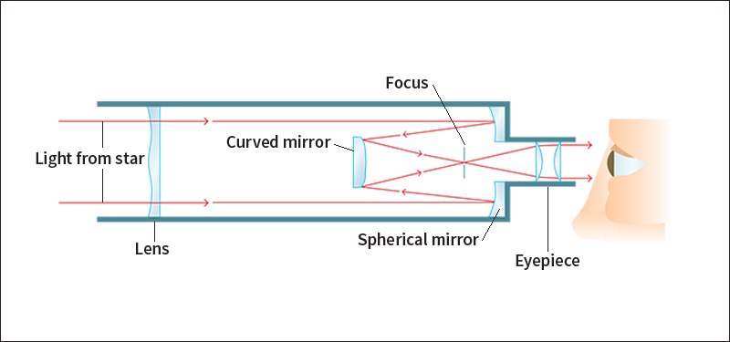
Bernhard Schmidt, an Estonian optician, invented the catadioptric telescope in 1930. This telescope forms images of a larger region of the sky than is possible with any other telescope design. Astronomers have used large Schmidt telescopes to photograph the entire sky.
Controlling a telescope.
To collect as much light as possible from a faint object, astronomers often focus a telescope on the object for several hours. Because Earth’s rotation causes the stars to appear to move overhead throughout the night, the telescope must move to remain focused on the object.
In older telescopes, a structure called an equatorial mount makes it easy to keep the telescope pointed at the object. A part of this structure called the yoke holds the telescope tube near the center of the tube. The tube pivots relative to the yoke, swinging up or down. The yoke rotates on a circular support whose axis is inclined at an angle parallel to Earth’s rotational axis. Once the tube is fixed on the object, there is no need to move the tube relative to the yoke. All that is necessary is to rotate the yoke at a rate equal and opposite to Earth’s spin. Thus, the equatorial mount is simple to use. However, it is large and expensive to build.
The development of modern computers has made it practical to use a smaller, less expensive mount called an azimuthal << az uh MYOOTH uhl >> mount. In this mount, the yoke rotates on a circular support that is vertical, rather than inclined. To keep the tube sighted on the object, both the yoke and the tube must move at variable speeds. A computer calculates the speeds and controls the movements.
Analyzing spectra.
Telescopes use spectrographs with CCD’s or photographic film to produce images of spectra and measure the brightness of each of their colors. Astronomers find much information in dark and bright spectral lines. When a spectrum of visible light is spread out horizontally, spectral lines appear as thin, vertical lines in various locations across the spectrum. The entire spectrum, considered as a whole, also contains information about the object that emitted the light.
Light is a form of energy, and the dark lines, known as absorption lines, arise when light energy passes through a group of atoms. The atoms absorb fixed units of energy—that is, photons. Because this energy is removed from the passing light, absorption lines appear in the spectrum. Each chemical substance has its own pattern of lines. Thus, the spectrum indicates the composition of the object through which the light passes. Astronomers have analyzed the absorption lines of sunlight, for example, to determine what elements are present in the sun’s surface layer, the photosphere.
The bright spectral lines, called emission lines, occur when hot atoms emit photons. Emission lines in the spectrum of the corona, the outer edge of the sun’s atmosphere, indicate the presence of iron atoms heated to millions of degrees.
An analysis of the entire band of radiation can also reveal an object’s temperature. The various colors of light spread out across the spectrum according to their energy. In the visible spectrum, for example, the lowest-energy color, red, is at one end. At the other end is violet, the highest-energy color—but scientists refer to this end of the spectrum as the blue end, named after the color next to violet. The spectrum of a relatively cool star is more intense at the red end, while the spectrum of a relatively hot star is more intense at the blue end.
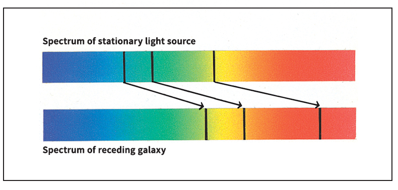
Spectral analysis can reveal an object’s speed due to a phenomenon known as Doppler redshift. In the spectrum of any object moving toward or away from Earth, the spectral lines are shifted from where they would appear in the spectrum of a stationary object. If the object is approaching Earth, the lines shift toward the blue end of the spectrum. If the object is moving away, the lines shift toward the red end. See Redshift.
Adaptive optics systems
are coming into use to correct atmospheric blurring in ground-based telescopes. The heating and cooling of the atmosphere produces blurring by distorting the wave front of light from an astronomical object. Some segments of the wave front get ahead of the main wave front and other segments lag behind. Adaptive optics systems correct a wave front before it reaches the focus of the telescope.
The first task in correcting a wave front is to make an electronic map of it as it comes into the telescope. A device called a wave front sensor provides the data for the map. In a natural guide-star system, the sensor uses a bright star whose position in the sky is close to the object being observed by the telescope. The atmosphere distorts a wave front coming from the guide star in almost exactly the same way in which it distorts a wave front coming from the object being observed.
Inside the sensor, tiny lenses focus different parts of a wave front from the guide star onto a CCD. Electronic signals representing this wave front travel to a computer, which “draws” the map.
As a wave front from the object being observed travels through the telescope, it reflects off a special mirror called a deformable mirror. Actuators controlled by the computer can change the shape of this mirror several hundred times each second. When the map indicates that one segment of the wave front is too far ahead, the computer moves the corresponding area of the deformable mirror back. The wave front segment must now travel farther. The main part of the wave front therefore can catch up with it. Similarly, a wave front segment that lags behind can catch up by reflecting from an area of the mirror that has been moved forward. In this way, the system can remove the wave front distortion.
If there is no bright star close enough to the object being observed, astronomers shoot a laser beam into the sky close to the object. The beam scatters off atoms at the top of the atmosphere and returns to the system, appearing as an artificial “star.”
Radio and microwave telescopes
Radio telescopes collect and measure faint radio waves given off by objects in space. American engineer Karl G. Jansky discovered radio waves from space in the early 1930’s. In the late 1930’s, Grote Reber, another American engineer, built the first bowl-shaped radio telescope and operated it in his backyard. Early radio telescopes found that the sun and the center of our galaxy were strong sources of radio waves. They also detected strong radio waves coming from dark areas of space. These sources were discovered to be the remains of exploded stars and a rare type of distant galaxy.
Since then, astronomers using radio telescopes have discovered objects that had been missed by optical telescopes. These discoveries include giant clouds of gas molecules; pulsars, collapsed stars that send out radio waves that arrive at Earth as regular pulses; and quasars, extremely distant starlike objects that produce enormous amounts of radiation.
How radio telescopes work.
Most radio telescopes collect radio waves with a large reflector, often called a dish antenna or simply a dish. The dish has the same shape as the parabolic mirror of a reflecting telescope. Radio waves, however, are much longer than light waves. As a result, a radio telescope’s dish need not be polished or shaped as accurately as the mirror of a reflecting telescope. But it must be much larger in diameter to collect the radio waves.
The reflector focuses the waves onto an antenna that translates them into electric signals. The signals contain information on the intensity of waves of different frequencies. A radio receiver amplifies the signals and sends them to a computer. The computer analyzes the radio spectrum of the wave source or produces an image of the source.
Types of radio telescopes.
In most radio telescopes, motors turn the dish toward an object in the sky. The largest moving-dish telescopes measure 330 feet (100 meters) across. One such telescope is in Effelsberg, Germany, near Bonn, and the other is in Green Bank, West Virginia.
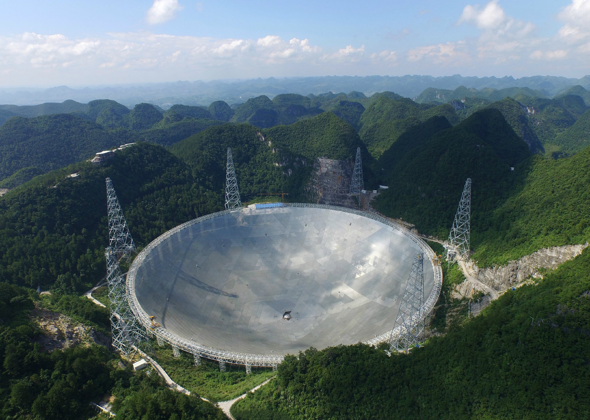
Astronomers use fixed-dish telescopes to study objects that are faint in the radio spectrum. The largest radio telescope is a fixed dish built into a valley in Guizhou Province, China. The dish is 1,600 feet (500 meters) in diameter. Scientists use it to locate pulsars and fast radio bursts (extremely short, intense bursts of radio waves).
Because the wavelength of radio waves is much longer than that of visible light, the resolution of a radio telescope is much lower than that of an optical telescope of the same diameter. However, a technique known as radio interferometry can produce extremely sharp images. This technique works best with many dishes spread out over long distances. The telescopes, considered as a unit, are called a radio interferometer, and the longest distance between dishes is the baseline.
In radio interferometry, computers at a central station combine data from the various dishes. First, however, the computers must introduce time delays into the data. The delays are necessary because each wave front comes in at an angle and therefore strikes the dishes at different times. The delays make up for the time differences. The combined data are equivalent to what would be received from a single dish that was much larger than any individual dish in the interferometer. The longer the interferometer’s baseline is, the better is the resolution of the interferometer.
The most sensitive ground-based radio interferometer is the Very Large Array (VLA), which stands on a high plain near Socorro, New Mexico. The VLA has 27 movable dishes, each 82 feet (25 meters) in diameter. The VLA’s full name is the Karl G. Jansky Very Large Array. The sharpest ground-based radio images come from the Very Long Baseline Array (VLBA), a system of 10 reflectors spread across one side of Earth. Their locations range from the Virgin Islands north to New Hampshire and west to Hawaii. As an interferometer, the VLBA is equivalent to a single dish with a diameter roughly equal to the diameter of Earth. 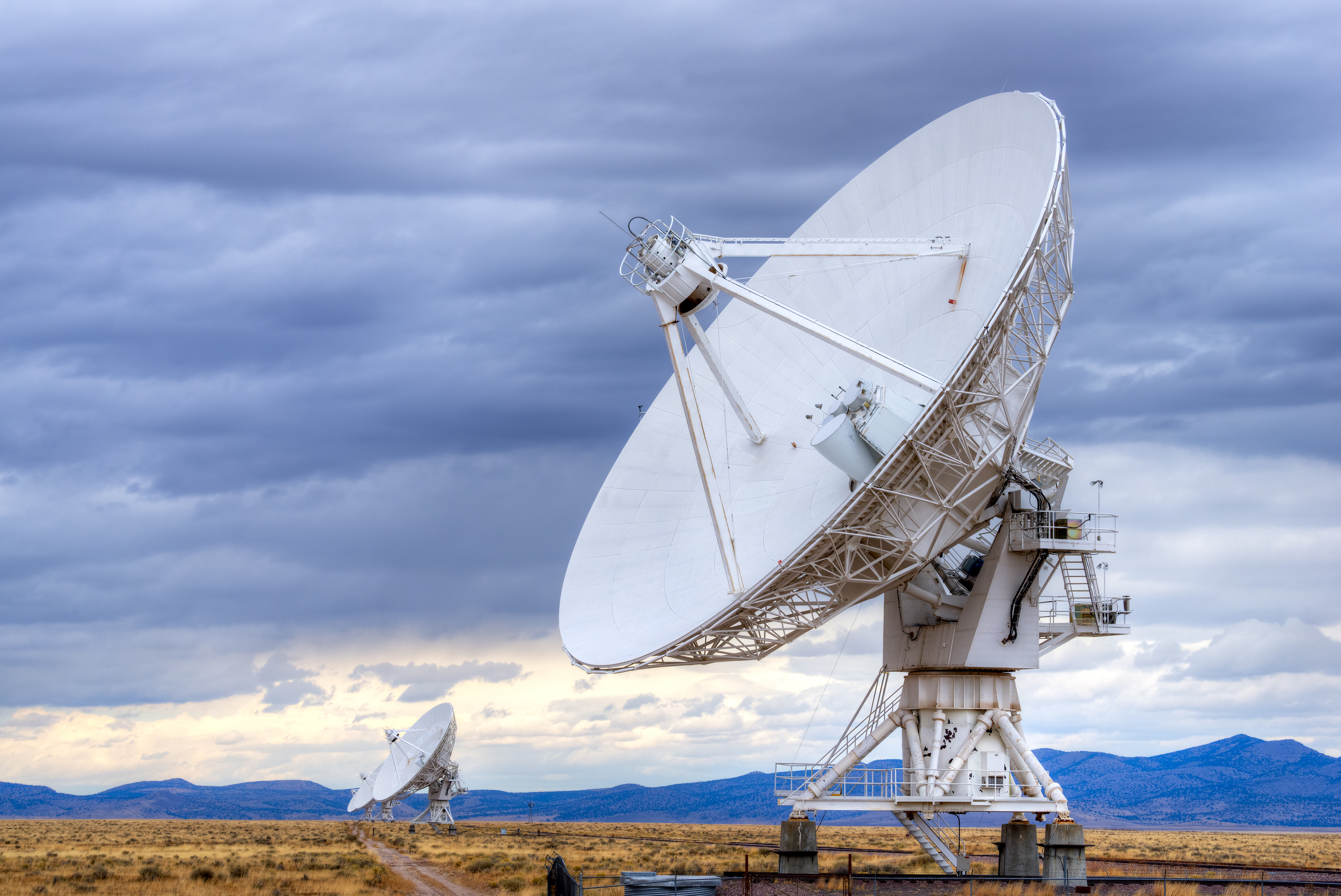
The Russian radio observatory Spektr-R operated in space from 2011 to 2019. Its telescope’s dish was 33 feet (10 meters) wide. Spektr-R’s replacement, Spektr-RG, was launched into space in 2019. Spektr-RG carries two complementary telescopes. One telescope can observe lower-energy X rays, and the other can observe higher-energy X rays. The two telescopes were designed to work together to produce an X-ray map of the sky.
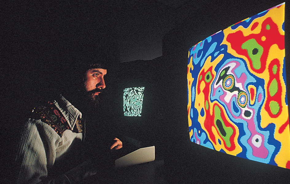
Microwave telescopes
work in much the same way as radio telescopes, and the two types are often considered together. However, microwaves have a shorter wavelength than radio waves, allowing for smaller reflectors. This enables astronomers to more easily mount microwave detectors onto satellites or high-altitude balloons.
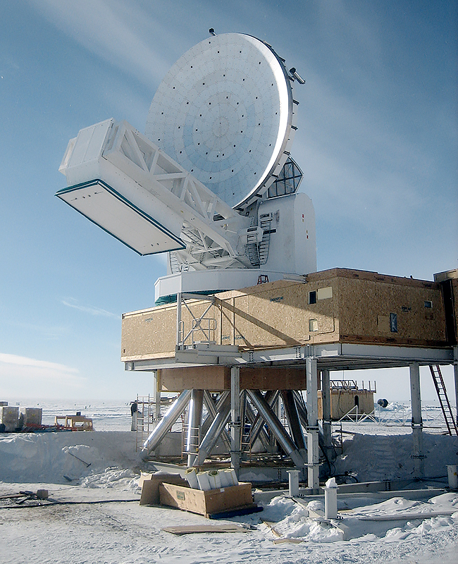
In 1964, the American radio astronomers Arno A. Penzias and Robert W. Wilson discovered the cosmic microwave background radiation (CMB) using a microwave telescope. Scientists believe this discovery is the first direct evidence of the big bang, the cosmic explosion that started the expansion of the universe.
Infrared telescopes
An infrared telescope collects infrared (heat) rays from objects in space. Most infrared telescopes are reflecting optical telescopes equipped with an electronic device called an infrared array detector instead of a CCD. But infrared telescopes have two special requirements: (1) parts of them must be kept cold while they operate, and (2) the telescopes must be located at high altitudes. 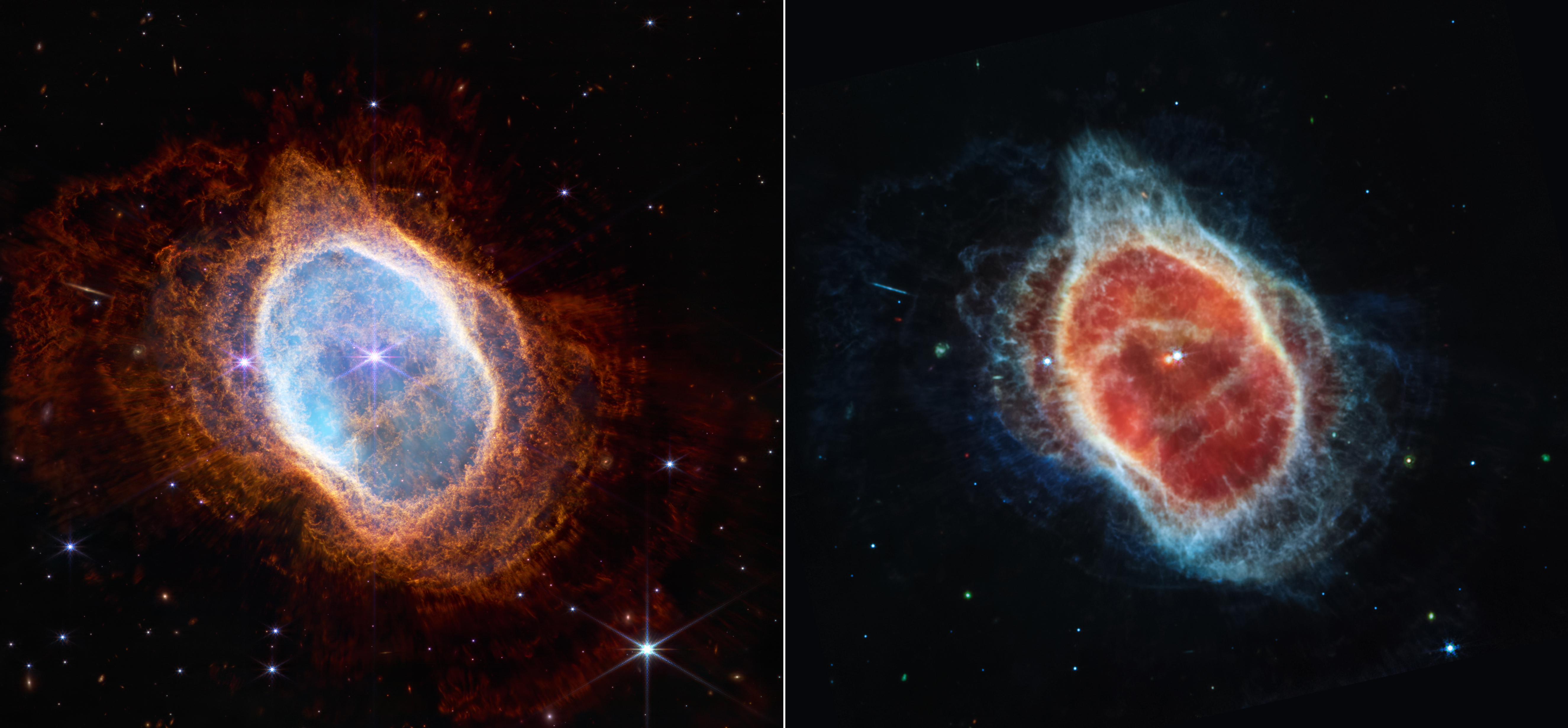
The cooling is necessary because any object that is at room temperature gives off tremendous amounts of infrared rays. Even heat from the telescope itself could interfere with the radiation from space.
High altitudes are necessary because water vapor and carbon dioxide in the atmosphere block infrared rays of many wavelengths. Astronomers build infrared telescopes on mountaintops where the air is thin and dry. They also send such telescopes into space on satellites.
In 1961, American physicist Frank J. Low built the first infrared detector sensitive enough for general use in astronomy. The device, called a bolometer, was an electronic thermometer housed in a vacuum and cooled to an extremely low temperature. When infrared rays hit the device, it warmed up and emitted an electric signal.
An infrared telescope operated in orbit aboard the Infrared Astronomical Satellite (IRAS) from January to November 1983. Liquid helium cooled the telescope to only a few degrees above absolute zero (–459.67 °F or –273.15 °C). IRAS found rings of dust around the star Vega and other nearby stars that might be developing solar systems.
In 2006 and 2007, the Japan Aerospace Exploration Agency’s AKARI telescope satellite produced an infrared map of nearly the entire sky. AKARI’s higher resolution enabled it to see smaller features than did IRAS.
An infrared observatory called the Stratospheric Observatory For Infrared Astronomy (SOFIA) was jointly developed by NASA and the German Aerospace Center. SOFIA, a modified Boeing 747SP aircraft with a 100-inch (250-centimeter) telescope, was designed to fly above most of Earth’s infrared-blocking atmosphere. In 2019, SOFIA detected the first type of molecule ever formed in the universe, helium hydride. Scientists believe that about 100,000 years after the big bang, helium and hydrogen combined to make helium hydride for the first time.
Other telescopes
Telescopes that detect the electromagnetic radiation with the shortest wavelengths—the shortest ultraviolet rays and all X rays and gamma rays—look different from other telescopes. These rays have so much energy that a normal parabolic mirror cannot reflect them. As a result, the telescopes have unusual mirrors or no mirror at all.
In addition, the atmosphere absorbs all gamma rays and X rays and all but the longest ultraviolet rays. To detect these rays, astronomers therefore send telescopes into space on satellites.
Ultraviolet telescopes.
A parabolic mirror can reflect all ultraviolet rays but those with the shortest wavelengths almost as well as it can reflect visible light. Astronomers therefore use reflecting telescopes in space to detect the longer-wavelength rays.
However, extreme ultraviolet rays, those with the shortest wavelengths, can reflect off a mirror at only a small angle called a grazing incidence. The reflection of a ray at a grazing incidence is like the skipping of a stone off the surface of a pond. Telescopes that detect extreme ultraviolet rays have mirrors that resemble a group of short tubes nested within one another. The rays reflect off the inner surfaces of the individual mirrors and then proceed to the focal plane.
Astronomers use ultraviolet telescopes to study extremely hot objects, such as quasars and stars called white dwarfs. Other uses include investigations of how stars form and the study of the composition of the gas between the stars.
X-ray telescopes.
The X rays that have the shortest wavelengths can pass straight through the materials that make up most telescope mirrors. But the longer-wavelength X rays, like extreme ultraviolet rays, will reflect at a grazing incidence. A number of X-ray telescopes therefore resemble telescopes that detect extreme ultraviolet rays.
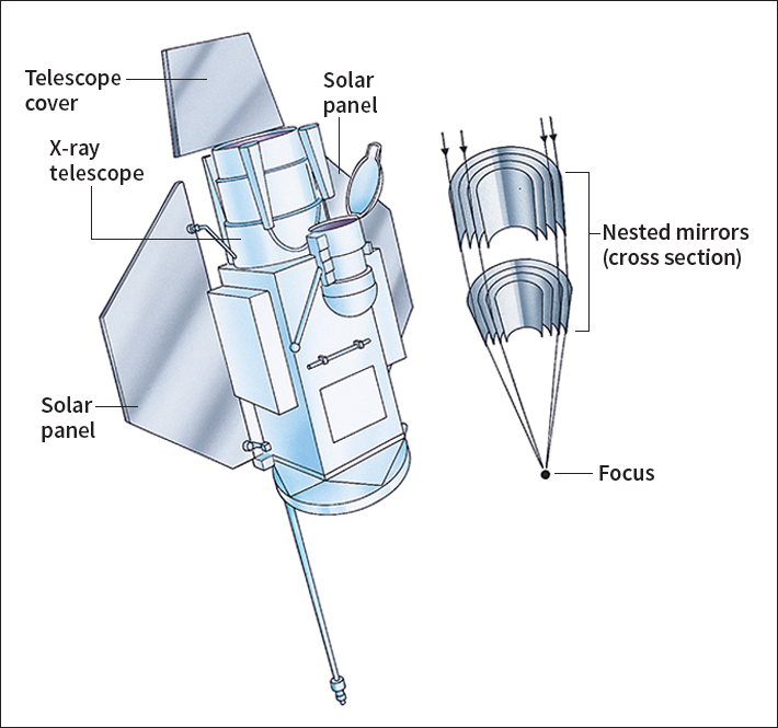
The simplest X-ray telescopes, however, have no mirror. Instead, they have an arrangement of iron or lead slats. The slats block all X rays except those from one line across the sky. The rays that enter the telescope go to a detector filled with a gas that absorbs X rays. An electronic device inside the detector counts the number of times the X rays interact with the gas. By scanning the sky, these telescopes can locate sources of X rays.
Many of the brightest X-ray sources are pairs of stars that orbit each other. In these pairs, one of the stars has collapsed to become a small, dense star called a neutron star or a black hole—an invisible object with such powerful gravitational force that not even light can escape its surface. The collapsed star pulls gas off the other star. When gas falls into the collapsed star, the gas emits the X rays.
Gamma-ray telescopes.
Gamma rays have the highest energy of any electromagnetic radiation. When a gamma ray passes through a group of atoms, it can produce a shower of subatomic particles and low-energy radiation. The shower travels in the same direction as the original gamma ray and is detected with devices called scintillators. A scintillator produces a flash of light that can be recorded. By analyzing the recorded data, scientists can calculate the energy level of the gamma ray and the direction of its source.
Gamma-ray telescopes on the Compton Gamma Ray Observatory, which was in orbit from 1991 to 2000, enabled scientists to learn more about some of the least understood objects in the universe. These objects included pulsars and quasars. In 1997, a gamma-ray satellite called BeppoSAX helped astronomers find the source of a burst of gamma rays that was the most powerful explosion ever detected.
The High Energy Transient Explorer-2 (HETE-2), a satellite launched in 2000, detected gamma-ray bursts and computed the locations of their sources. The satellite immediately sent this information to a ground-based communication system. Within seconds of the detection of a source, optical telescopes on the ground could begin to study the source.
A satellite known as INTEGRAL (International Gamma-Ray Astrophysics Laboratory) carries devices that can detect an object’s gamma rays, X rays, and visible light at the same time. INTEGRAL was launched in 2002.
In 2004, scientists launched a satellite called Swift. The spacecraft uses a wide-angle gamma-ray telescope to detect gamma-ray bursts. Swift can then quickly adjust its position to point an X-ray telescope and a combined ultraviolet and optical telescope at the source of the burst.
In 2008, scientists launched the Fermi Gamma-ray Space Telescope. This orbiting observatory was designed to be more sensitive and to gather data faster than previous gamma-ray instruments.
